Table of Contents
- MKE Lower Receiver Fitment Guide for Builders: What Actually Matters
- AR-15 Lower Receiver Compatibility Chart: Mil-Spec vs. Proprietary MKE Specs
- Precision Firearm Assembly Tools You Need Before You Start
- Troubleshooting Lower Receiver Pin Alignment: Causes and Fixes
- Tolerance Stacking and Material Differences in MKE Lowers
- Buffer Assembly and Receiver Extension Fitment
- Common Fitment Mistakes and How to Avoid Them
- Frequently Asked Questions
Last Updated: September 26, 2026
MKE Lower Receiver Fitment Guide for Builders: What Actually Matters
An MKE lower receiver is a Turkish-made AR-15 pattern lower built to metric specs that often sit just outside the tolerance windows American builders expect. That explains most fitment headaches, and why a dedicated MKE lower receiver fitment guide for builders must cover pin diameters, clearances, and tolerance stacking rather than generic assembly steps.
AR-15 Lower Receiver Compatibility Chart: Mil-Spec vs. Proprietary MKE Specs
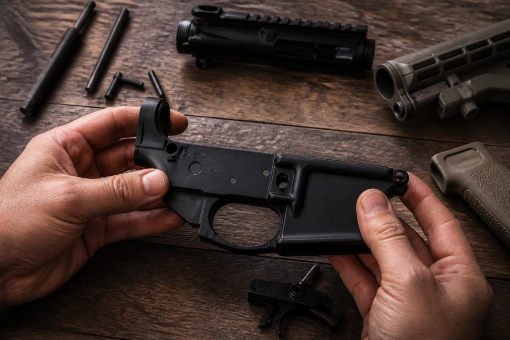
MKE lowers generally accept standard mil-spec parts, but the receiver itself is not guaranteed to hold the same tolerances as a forged US-made lower. Treat it as mil-spec compatible, not mil-spec identical. Differences show up in pin hole diameters, trigger group clearances, and receiver extension threads.
| Feature | Mil-Spec Expectation | MKE Reality to Check |
|---|---|---|
| Trigger/hammer pin holes | 0.154 in nominal | Verify with pin gauge |
| Pivot and takedown pin fit | Snug, hand-press | May need light fitting |
| Trigger group clearance | Drop-in | Check for contact |
| Receiver extension threads | 1-3/16-16 | Confirm thread engagement |
| Safety selector bore | Free rotation | Check detent channel |
Pin Hole Diameters and Trigger Group Clearances
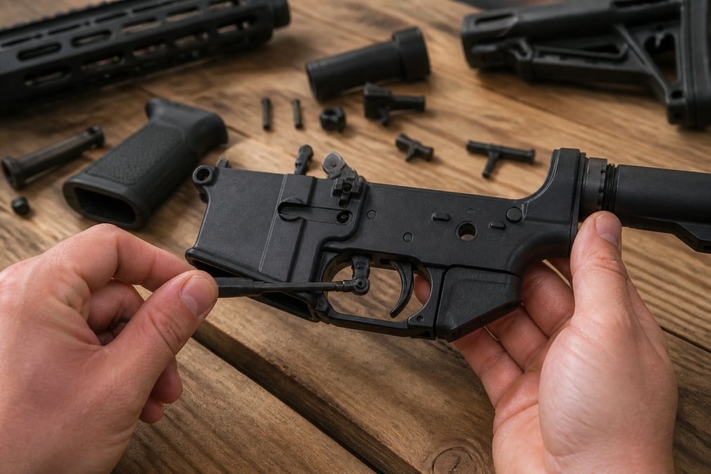
Measure before you install anything. A pin gauge set tells you in two minutes whether your trigger pins will walk or hold. If the hammer pin drops through with no resistance, you have a problem; if it needs a punch to seat, you have a different one. Both are fixable, but neither after you’ve staked the pin. Dry-fit the hammer and trigger without springs first, any contact between the disconnector and the receiver floor shows up later as a heavy, gritty pull.
Precision Firearm Assembly Tools You Need Before You Start
Here’s the short list that actually matters:
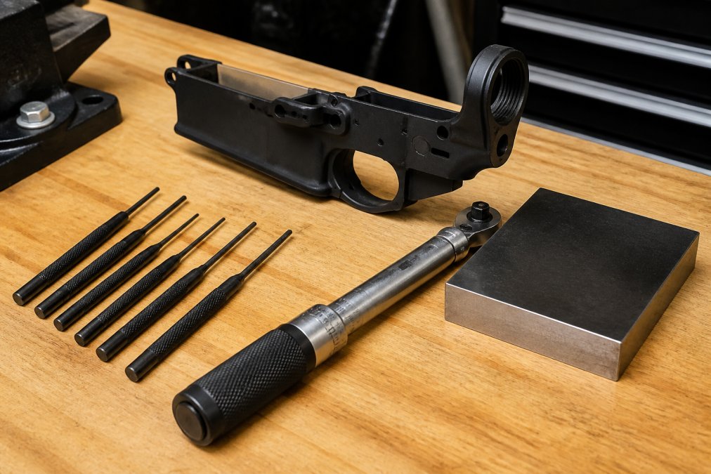
- Roll pin punch set (1/16, 5/64, 3/32)
- Bench block with receiver saddle
- Trigger pin install tool
- Torque wrench rated to 40 in-lb
- Pin gauges for hole verification
- Safety selector install tool
- Nylon and brass drift punches
- Quality assembly grease
Buy a pin gauge set before your first MKE build. It costs less than a replacement lower and tells you in seconds whether you’re dealing with an undersized hole or a pin that’s out of spec.
Skip cheap punch sets for roll pins, they mushroom the heads and you’ll be drilling them out.
Troubleshooting Lower Receiver Pin Alignment: Causes and Fixes
Pin misalignment on an MKE lower is rarely a single failure. It is almost always one of four conditions: a burr in the pin hole, an out-of-spec pin, a trigger group sitting proud of the receiver floor, or tolerance stacking between receiver and parts kit. Diagnose before you touch a punch, the wrong fix turns a ten-minute correction into a ruined receiver.
Work through this sequence in order.
- Swab the hole. A cotton swab dragged through the trigger and hammer pin holes catches on any burr. If it snags, deburr by hand with a 0.154 in reamer turned by finger pressure only, never chuck it in a drill, which ovals the hole.
- Test the pin without the trigger installed. Drop the trigger pin through the bare receiver. If it falls free with no drag, the pin diameter is fine and your problem is alignment, not size. If it hangs up, measure the pin against the 0.154 in nominal and compare to the hole with a pin gauge.
- Install the trigger group with a slave pin. A slave pin holds the trigger and disconnector in alignment while you drive the real pin. If the real pin seats with the slave pin but not without it, the trigger group is shifting under spring tension, common on MKE receivers where the trigger slot is cut a few thousandths wide.
- Measure receiver flex across the magwell. Clamp the receiver in a bench block and measure magwell width at top and bottom with calipers. If the spread exceeds a few thousandths of an inch, the walls are flexing under pin pressure and no reaming will fix it, a receiver-level problem, not a parts problem.
When Pins Walk: Roll Pin and Hammer Pin Fixes
Pin walk is the most common complaint on any AR build, and MKE receivers are not immune. A walking hammer pin means the pin-to-hole fit is loose enough that recoil vibration walks it out over a range session: if the interference fit is below roughly 0.0005 in, that load wins.
The fix depends on which pin is walking:
- Hammer pin walk: Install anti-walk pins (set screws that thread into the receiver’s pin holes), the standard, reversible fix. If the hole is only slightly oversized, oversized pins (0.1555 in and 0.156 in) restore interference without permanent modification.
- Trigger pin walk: Same approach, anti-walk pins are the standard fix. Do not mix an anti-walk hammer pin with a standard trigger pin; the set screws are a matched pair and mismatched hardware can back out under recoil.
- Roll pin walk: Rare, but if the bolt catch roll pin walks, replace it and stake it with a proper roll pin punch. A mushroomed head from a cheap punch set is a common cause.
Never stake a hammer pin to stop walk. It works once. Then you can’t remove the pin without drilling it, and you’ve ruined the receiver for future upgrades. Anti-walk pins cost less than a replacement lower and they come out with a hex key.
Reading Wear Points Before You Fix Anything
Before installing any corrective part, inspect the wear pattern on your existing pins. Polished bands near both ends with a dull center means walking. A single bright spot on one side means binding against a burr. Galling or smeared metal means undersized and rotating under load. The pattern tells you which fix to apply, thirty seconds with a magnifier.
Tolerance Stacking and Material Differences in MKE Lowers
Tolerance stacking is what happens when several parts that are each within spec combine to produce a fit that isn’t. Every individual dimension passes inspection; the assembly doesn’t. It is the single most useful concept for anyone building on an MKE lower, because MKE receivers tend to sit at the edge of the tolerance window rather than the center.
How to Measure Your Stack Before You Build
You need two tools: a pin gauge set and calipers that read to 0.0001 in. Both cost less than a replacement lower.
- Measure the hole. Insert pin gauges in 0.0005 in increments until you find the largest gauge that passes through the hammer pin hole with light drag. That is your actual hole diameter.
- Measure the pin. Use calipers on the hammer and trigger pins at three points along the shank and average them. Pins are not always round, one that measures 0.1540 in on one axis can measure 0.1535 in on another.
- Subtract. Hole minus pin gives your actual clearance. Negative (pin larger than hole) means interference and the pin must be pressed. Positive by more than 0.001 in means pin-walk territory, plan for anti-walk or oversized pins before assembly.
- Repeat for the trigger pin and safety selector bore. The selector is the one builders forget, and a selector that rotates with grit or won’t click into detent is almost always a stack problem, not a detent spring problem.
Record your measurements on a piece of tape stuck to the bench. When a pin walks six months later, you will know whether the hole was always oversized or whether something changed. Most builders never measure, which is why most builders can’t diagnose.
Material Science: 7075-T6 vs. 6061 Aluminum and What It Means for Fitment
Most MKE lower receivers are machined from one of two aluminum alloys, and the choice affects long-term fitment more than most builders realize.
How Anodizing Thickness Changes Your Measurements
Anodizing is not paint. It is a conversion coating that grows into the aluminum surface and adds roughly 0.0005 in to 0.001 in of thickness per surface, depending on Type II versus Type III (hardcoat). That thickness matters at every pin hole and bore. A receiver that measured 0.1540 in at the hammer pin hole before anodizing can measure 0.1530 in after, because the coating grows inward as well as outward.
Tolerance stacking is not a theoretical concern on MKE lowers, it is the mechanism behind most fitment complaints. Measure the hole, measure the pin, subtract, and plan your hardware around the result. Material choice (7075-T6 vs. 6061) determines how those measurements hold up over time, and anodizing thickness determines what the measurements actually are when the receiver reaches your bench.
Buffer Assembly and Receiver Extension Fitment
The buffer assembly is where fitment problems get loud. A receiver extension that threads in hard, a castle nut that won’t torque, or a buffer that binds in the tube all point to the same class of issue.
Check these in order:
- Thread the receiver extension in by hand first. If it binds before it seats, stop and inspect the threads.
- Torque the castle nut to spec, then stake it.
- Test buffer travel with the spring installed. It should move freely with no scraping.
- Install the end plate and confirm the receiver extension is timed correctly for your stock.
Buffer tube fitment problems are almost always traceable to either thread engagement or tube roundness. Hand-thread first, torque second, and never force a castle nut.
Common Fitment Mistakes and How to Avoid Them
The mistakes that cost builders the most time are almost always preventable:
- Forcing pins that don’t want to seat. Stop. Diagnose. Then install.
- Skipping the pin gauge check. Two minutes saves two hours.
- Mixing parts from different kits without checking fit. Tolerance stacking doesn’t care which box the part came from.
- Over-torquing the castle nut. You’ll crack the receiver extension threads.
- Not test-fitting the safety selector before installing the grip. The detent channel is easier to inspect with the grip off.
- Assuming mil-spec means identical. Compatible is not identical.
Frequently Asked Questions
Are MKE lower receivers compatible with standard mil-spec parts kits?
MKE lower receivers are designed to accept standard mil-spec parts kits, but fitment can vary by batch. Most builders find that mil-spec trigger groups, safety selectors, and bolt catches drop in without modification. However, you should always test-fit your lower parts kit before final assembly. If a pin requires excessive force, stop and check for burrs or coating buildup in the pin holes rather than forcing it. A compatibility chart from your receiver manufacturer helps confirm which kits work best.
What are the common tolerance issues when fitting MKE lower receivers?
The most frequent tolerance issues involve pin hole diameters, trigger pocket depth, and buffer tube threading. Pin holes that run undersized make trigger and hammer pin installation difficult, while oversized holes cause pin walk during cycling. Trigger pocket depth affects safety selector rotation and disconnector timing. Tolerance stacking, where small variances across multiple parts compound, is the root cause in most builds. Measure pin holes with calipers before assembly and compare against mil-spec dimensions to catch problems early.
What tools are required for proper lower receiver fitment?
You need roll pin punches in 1/16, 3/32, and 1/8 inch sizes, a nylon or brass mallet, a bench block, and a torque wrench that reads inch-pounds for the castle nut. Calipers help verify pin hole diameters and detect tolerance stacking before it causes problems. A pivot pin installation tool saves time and prevents scratches. For precision firearm assembly, a good armorer’s wrench and a set of hollow ground screwdrivers round out the kit. Avoid using standard punches, which can deform roll pins and mar the receiver.
How do I troubleshoot trigger group alignment in an MKE lower?
Start by installing the trigger and hammer pins without springs to check free rotation. If the pins bind, inspect the pin holes for burrs or anodizing buildup. A reamer sized to mil-spec clears minor obstructions. If the disconnector drags, check the trigger pocket depth and the disconnector spring seat. Pin walk during cycling usually means the pin holes are slightly oversized or the hammer spring legs are not seated correctly in the receiver. Always perform a function check after any adjustment.
What is the difference between forged and billet MKE lower fitment?
Forged lowers are pressed from 7075-T6 aluminum and typically hold tighter tolerances because the forging dies are machined to mil-spec dimensions. Billet lowers are cut from a solid block, which allows custom features but can introduce more variation in pin hole placement and trigger pocket geometry. For fitment, forged receivers usually require less hand-fitting with standard parts kits. Billet lowers may need minor deburring or reaming. Both materials work well, but check the manufacturer’s tolerance specs before buying a parts kit.
Do MKE lowers require specific buffer tube threading or compatibility?
MKE lowers use standard mil-spec receiver extension threading, so most buffer tubes and castle nuts fit without issue. However, some builders report that certain aftermarket buffer tubes have slightly different thread pitch or coating thickness that affects fitment. Always test-thread the receiver extension by hand before applying torque. The castle nut should thread on smoothly and seat against the end plate. If it binds, check for debris in the threads or a misaligned end plate. Torque to mil-spec values using an armorer’s wrench.