Last Updated: October 24, 2026
Quick Summary
To measure firearm part tolerances, use digital calipers to take multiple readings along the feature, zero the tool before measuring, establish a consistent reference surface as your datum, and compare your measurements to the specification range. Parts within specification should fit together properly; parts outside tolerance may cause binding or fitment issues.
- Digital calipers read to 0.01 inches and cost under $30, making them the most practical tool for most builds.
- Measure at least three points along a feature to reveal taper or out-of-round conditions that a single reading would miss.
- Always zero calipers with jaws closed before measuring and check calibration monthly against a known standard.
- Record the date, tool, datum, temperature, and all three readings so measurements can be reproduced and compared later.
- Parts within tolerance should fit snugly without forcing; if assembly requires a hammer or vice, something is out of tolerance or misaligned.
Table of Contents
- Understanding Firearm Part Tolerances and Why They Matter
- How to Measure Firearm Parts with Calipers
- Firearm Part Clearance vs. Tolerance: What’s the Difference?
- How to Calculate Dimensional Tolerances for Your Build
- Firearm Part Fit and Compatibility: Checking Your Measurements
- Tools and Techniques for Reliable Firearm Part Measurement
- Common Mistakes When Measuring Firearm Part Tolerances
- Verifying Your Firearm Parts Meet Specification
- Get Started With Precision Components
- Frequently Asked Questions
Understanding Firearm Part Tolerances and Why They Matter
Firearm part tolerances are the allowable dimensional variations in components, how much a part can deviate from spec while still functioning.
Tolerances matter because components must work together precisely. A barrel 0.005 inches too large might not chamber; a trigger with excessive clearance could fail under stress.
The relationship between tolerance and fit determines everything. A clearance fit allows parts to move freely. An interference fit requires force to assemble.
NIST Guide to the Expression of Uncertainty in Measurement
How to Measure Firearm Parts with Calipers
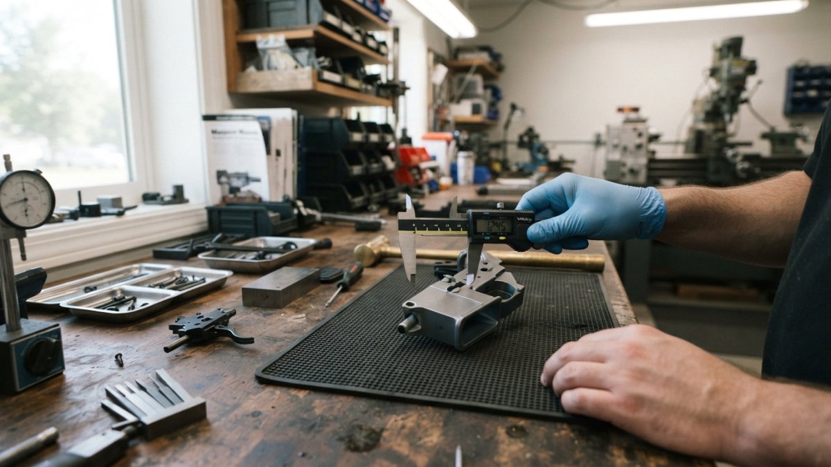
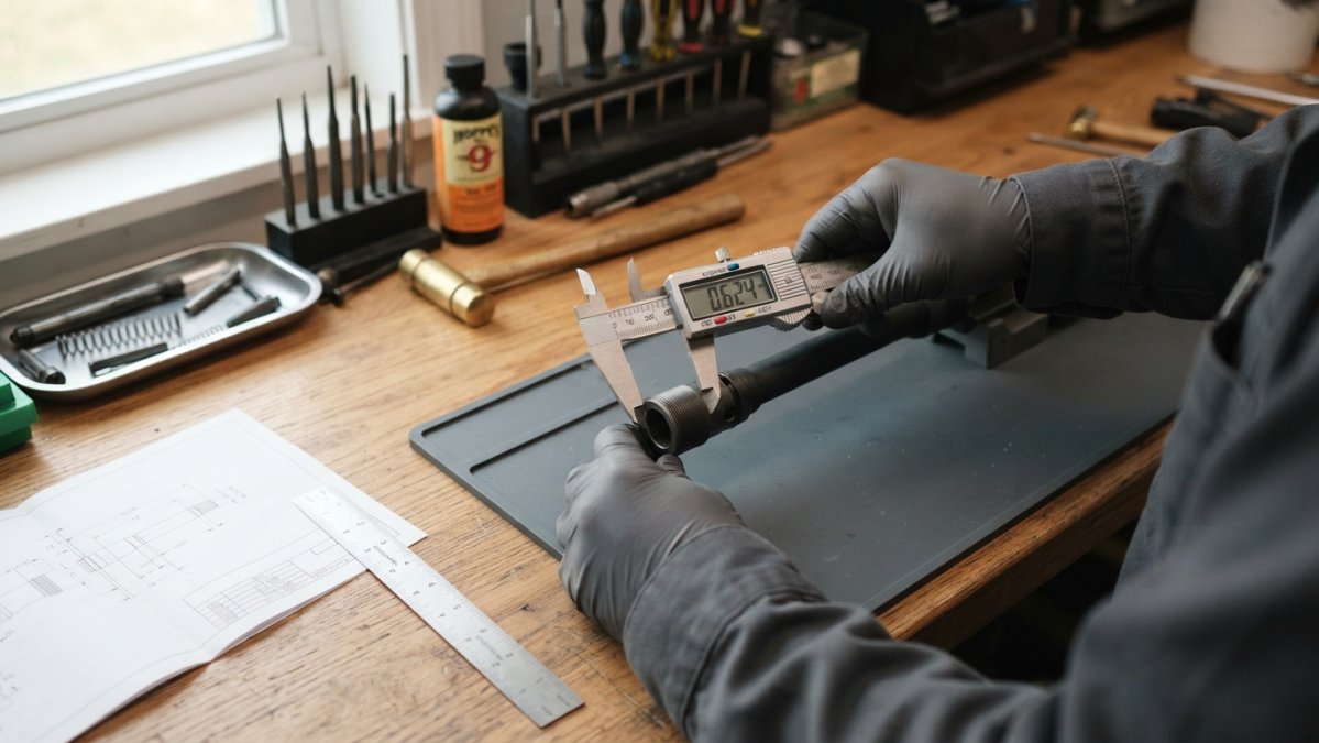
Digital calipers are the most practical tool for firearm part measurement, affordable, portable, and accurate enough for most builds. A quality caliper reads to 0.01 inches, but the tool is only half the job; the other half is a repeatable workflow that produces numbers you can trust.
A Repeatable Measurement Workflow
A fixed sequence reduces error more than any single tool upgrade. Use this order every time:
- Prepare the part. Clean the measuring surfaces with a lint-free cloth. Remove oil, carbon, and debris. Let the part stabilize to room temperature, metal expands and contracts, and a part pulled from a cold truck or a hot trunk will read differently than one at 68°F.
- Prepare the tool. Zero the calipers with the jaws closed and check that they meet evenly with no visible gap. If the display does not return to zero, fix the tool before measuring.
- Establish a datum. Choose a reference surface and measure from it consistently, the breech face for barrel length, a machined flat face for receiver dimensions. Write the datum down.
- Measure at multiple points. Take at least three readings along the feature, near each end and at the middle of a barrel. Parts are rarely uniform, and a single reading can hide taper or out-of-round.
- Record the reading and the conditions. Note the date, tool, datum, and ambient temperature, a measurement without context is hard to reproduce.
- Compare to specification. Only after recording should you judge pass or fail against the drawing or manufacturer range.
Setting Up Your Calipers for Accuracy
Before you measure anything, zero your calipers: close the jaws completely and press the zero button.
Clean the measuring surfaces before each use, dirt or debris between the jaws throws off your measurement.
Handle calipers gently. Dropping them or forcing the jaws can damage the internal mechanism and destroy accuracy.
Check calibration monthly against a known standard, a calibration block or precision gauge pin, and any time the tool is dropped or shows a zero error.
Measuring Outside and Inside Dimensions
Outside diameter (OD) measurements are straightforward: place the part between the jaws, close them gently until contact, and read the display.
Inside diameter (ID) uses the inside-measuring jaws: open them inside the bore until they contact the sides.
Measure firearm overall length (OAL) by placing the part against a flat surface and extending the depth rod to the far end.
Understanding Resolution and Uncertainty
Resolution is the smallest change the display shows, 0.01 inches on a typical digital caliper. Uncertainty is the range within which the true value likely falls, always larger than resolution, roughly ±0.001 to ±0.002 inches under good conditions. If the tolerance band is ±0.002 inches and your tool uncertainty is ±0.002 inches, you cannot confidently judge the part; step up to a micrometer that reads to 0.001 inches, or send the part for professional inspection.
Measure the same feature three times and write down all three numbers. If they spread more than your tool’s expected uncertainty, your technique or the part is the problem, not the specification.
Firearm Part Clearance vs. Tolerance: What’s the Difference?
Clearance is the gap between two mating parts when assembled. Tolerance is the allowable variation in a single part’s dimension. Confusing them leads to fitment problems.
A clearance fit means parts can move relative to each other, you want clearance between a bolt carrier and its guide rails.
Tolerance defines how much a single part can vary.
Stack-up occurs when tolerances combine: if part A has a +0.002 tolerance and part B has a +0.003 tolerance, the total stack-up is 0.005 inches.
How to Calculate Dimensional Tolerances for Your Build
Start with the engineering drawing or manufacturer specification, which gives the nominal dimension and tolerance range. A spec might read “0.750 ± 0.005 inches,” meaning the acceptable range is 0.745 to 0.755 inches. Measure your part and compare: within range meets specification; outside is out of tolerance and may cause fitment issues.
Reading the Drawing Before You Calculate
Most firearm specifications use one of three dimensioning styles, and each changes how you judge a part:
- Limit dimensions show the high and low values directly, such as 0.745 / 0.755. Any reading between them passes.
- Plus/minus tolerances show a nominal value with an allowed deviation, such as 0.750 ± 0.005. Convert it to limits before you measure so you are comparing numbers to numbers.
- Geometric controls (GD&T) use feature control frames to limit form, orientation, and location, for example, a flatness or perpendicularity callout. A part can be within its size tolerance and still fail a geometric control. Plain-language rule: size tolerance controls the dimension; the feature control frame controls the shape and relationship.
Read the drawing notes too. Notes often carry fit classes, surface finish requirements, and inspection instructions that the dimensions alone do not show.
Calculating Stack-Up for Mating Parts
Stack-up is where tolerance math becomes useful. When several parts assemble in a line, their tolerances combine.
Example: a barrel extension seat has a +0.002/-0.000 tolerance, a bolt lug has a +0.003/-0.000 tolerance, and a receiver face has a ±0.001 tolerance.
A second method is statistical (root-sum-square) stack-up, which assumes variations are independent and rarely all hit their extremes at once.
Choosing a Reasonable Tolerance
For custom builds, identify the critical dimensions where parts must fit together, then assign tolerance ranges based on the fit type required:
- Clearance fits need looser tolerances, commonly ±0.010 to ±0.020 inches for non-critical interfaces.
- Transition fits need moderate tolerances, commonly ±0.005 to ±0.010 inches.
- Interference fits need tight tolerances, commonly ±0.001 to ±0.005 inches, and often require a press or thermal fit.
These ranges are starting points, not rules. The correct tolerance depends on the function of the joint, the materials, and the consequences of failure. A trigger pin hole and a cosmetic gap do not deserve the same tolerance.
Tolerance decisions on pressure-bearing or safety-critical components, chamber, locking lugs, barrel extension, fire control, should be confirmed against the manufacturer’s specification or by a qualified gunsmith. Do not invent a tolerance for a safety-critical interface.
Document your calculations, nominal dimension, tolerance range, stack-up method, and the reason for the tolerance choice. This helps you troubleshoot later and provides reference for future builds.
Firearm Part Fit and Compatibility: Checking Your Measurements
Once you’ve measured your parts, compare each dimension to its specification. Parts within specification should fit together properly.
ASME Standards for Geometric Dimensioning and Tolerancing
Assemble the parts dry first, without lubrication.
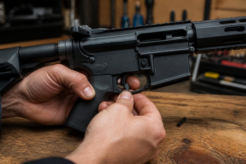
Test function after assembly: cycle the action, check trigger travel and reset, and verify all moving parts operate smoothly.
Learn how to verify your measurements apply to actual assembly with our detailed fitment guide for precision assembly techniques.
Tools and Techniques for Reliable Firearm Part Measurement
Selecting the Right Measurement Tools
Digital calipers are your starting point, affordable and accurate for most builds. A quality caliper costs under $30 and reads to 0.01 inches. Learn about the essential firearm maintenance tools you need to measure parts accurately and maintain your firearms properly.
Depth gauges measure bore depth and recesses. They’re useful for checking chamber depth or verifying pocket dimensions in lower receivers.
Micrometers read to 0.001 inches for higher accuracy than calipers.
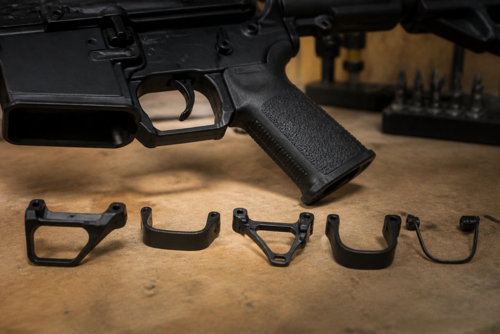
Feeler gauges measure small clearances, handy for checking trigger guard clearance or the gap between mating surfaces.
A machinist’s ruler provides a reference surface for measuring overall length or creating a flat datum.
| Tool | Accuracy | Best For | Cost |
|---|---|---|---|
| Digital Calipers | 0.01 inches | General measurement | $20-$40 |
| Depth Gauge | 0.01 inches | Bore depth, recesses | $15-$30 |
| Micrometer | 0.001 inches | Tight tolerances | $30-$80 |
| Feeler Gauges | Varies | Small clearances | $10-$25 |
Calibration and Datum Selection
Calibration keeps your tools accurate. Check your calipers monthly against a known standard.
Datum selection means choosing a reference surface and always measuring from the same point.
For receiver measurement, use a flat machined face as your datum to prevent error from curved or irregular surfaces.
Document your datum choice so you can repeat the same method later. Consistency matters more than perfection.
Common Mistakes When Measuring Firearm Part Tolerances
Forcing calipers closed is the most common error.
Measuring at only one point introduces error. Parts are rarely perfectly uniform.
Ignoring temperature effects is a hidden mistake, metal expands and contracts.
Failing to zero your calipers throws off every reading. Always zero first.
Mixing units causes confusion. Use inches consistently and don’t switch between decimal and fractional mid-measurement.
Not documenting your measurements means you can’t track trends or troubleshoot later.
Verifying Your Firearm Parts Meet Specification
Measure the part and compare to the specification range. Within range, the part is acceptable.
If outside the range, the part is out of tolerance.
Verify multiple parts from the same batch, measuring several tells you whether an out-of-spec part is isolated or systemic.
Test fit the parts together before finalizing your build.
Keep a measurement log recording every part, its dimensions, and pass/fail.
Precision Measurement Best Practices
Get Started With Precision Components
Learning to measure firearm part tolerances takes practice, but the fundamentals are simple: use quality tools, zero before measuring, measure multiple points, and compare to specification.
At Polymer Pew, our aluminum MKE lowers are tested for variant compatibility, and our triggers and safety kits are built to tight tolerances for consistent performance.
Get your precision firearm components here and eliminate fitment guesswork from your next build.
Frequently Asked Questions
What is the difference between tolerance and clearance?
Tolerance is the allowable variation in a dimension, the specified range a part can measure and still function correctly. Clearance is the physical gap between two mating parts when assembled. A part might have a tolerance of ±0.005 inches, while clearance describes how loose or tight the fit actually is. Understanding both ensures your firearm parts assemble reliably without binding or excessive play.
Which tools are best for measuring firearm parts?
Digital calipers (accurate to 0.01 inches) work well for general dimensions like barrel diameter and overall length. Micrometers provide greater precision (0.001 inches) for critical tolerances. Depth gauges measure bore diameter and internal clearances. For professional work, dial indicators and precision fixtures offer the best repeatability. Start with quality digital calipers, they’re affordable and sufficient for most custom builds and compatibility checks.
How do you check whether two firearm parts fit within tolerance?
Measure each part against its specification using calibrated tools. Compare your measurements to the manufacturer manual or engineering drawing. If both parts fall within their specified ranges, they should fit. Assemble them dry (without force) and check for binding or excessive gap. If the fit is too tight or too loose, one or both parts may be out of specification, and you should consult a qualified gunsmith before proceeding.
How do you measure firearm part tolerances accurately?
Use calibrated measurement tools and establish a consistent datum (reference point) for each dimension. Measure the same feature multiple times from the same position to verify repeatability. Record all measurements in decimal format for precision. Compare results to the manufacturer specification or engineering drawing. Document your process so you can repeat it, consistency matters more than perfection for most custom builds.